


When a crowded equipment pad becomes a technical problem
Pool equipment does not need to be arranged in a perfectly straight row to operate correctly. The layout becomes a problem when it prevents valves from moving, blocks access to serviceable parts, holds pipework under stress or makes the water path difficult to isolate and understand. These faults may not stop the pool immediately. A pump can continue running while its basket lid is trapped below a pipe, a salt cell can operate even though it cannot be removed, and a union can remain dry until vibration or thermal movement exposes poor alignment. The result is usually slower diagnosis, recurring leaks and more plumbing work when one component eventually needs attention.
A pool equipment pad has a layout problem when normal operation or maintenance requires forcing a valve, bending a pipe, cutting unrelated plumbing or removing another component first. Cosmetic untidiness alone is not enough to justify rebuilding it.
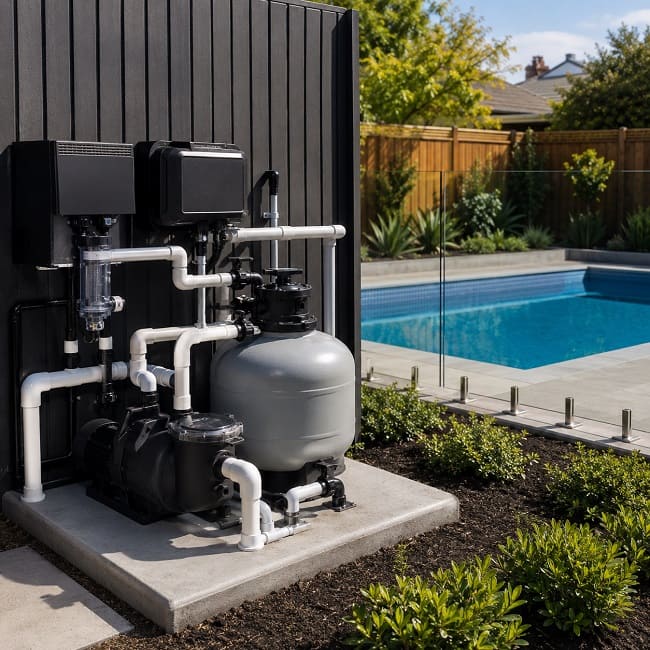
Four different types of layout problem
An inconvenient layout is not automatically a hydraulic fault or a safety defect. Separating the problem into the correct category helps determine whether the pad needs a small correction, partial rearrangement or wider rebuild.
Cosmetic
Pipes look uneven or cross each other, but all valves, lids, unions and service panels remain accessible and the circulation system operates normally.
Serviceability
Equipment works, but a basket, cartridge, salt cell, motor or access panel cannot be removed without disturbing other components.
Hydraulic
Valve position, pipe size, unnecessary restrictions, incorrect flow direction or a poorly arranged bypass affects circulation or equipment operation.
Safety or compliance
Water pools around electrical equipment, pressurised equipment cannot be accessed safely, or required electrical, gas or ventilation clearances are compromised.
Start by tracing the complete water path
Before judging valves or pipework, establish which lines carry water to and from the pool. A complicated pad often contains old solar, spa, cleaner or water-feature branches that are no longer obvious.
This is a reading guide, not a universal installation diagram. Heating equipment, salt cells, chemical feeders, check valves, bypasses and sensors have model-specific placement and flow requirements.
Valve problems that are easy to miss
A valve may look open while remaining partly restricted, and several visible valves do not necessarily provide complete isolation. Each valve must be assessed against the full water path.
The handle cannot reach its end position
A wall, pipe, controller or adjacent valve can stop the handle before the internal diverter reaches the intended position. This may reduce flow even though the handle appears broadly aligned with the pipe.
The lines are not identified
Unlabelled skimmer, drain, spa, cleaner and water-feature lines make controlled testing difficult. Photograph valve positions before changing them and label a line only after its function has been confirmed.
Water can still reach the component
A heater or chlorinator may appear isolated by two valves but remain connected through a bypass or shared return branch. Isolation should be tested logically before unions are opened.
The valve occupies the removal path
Valve bodies, handles and actuators should not sit above pump lids, filter clamps or salt-cell unions. Access must be checked with the component in the position required for removal.
A valve should not be forced because its handle feels stiff. Internal damage, debris or a seized seal can make the handle fail before the underlying problem is corrected.
Unions, alignment and hidden pipe stress
A union is useful only when the nut can be reached, the connection can separate and the component has somewhere to move. Poor alignment can turn a new union into a recurring leak point.
What happens when a union is released matters
With the pump stopped, stored pressure safely released and the component properly isolated, aligned union faces should remain close to their natural position. If one pipe springs sideways, drops or pulls away when the nut is loosened, the connection may have been carrying constant mechanical load.
Replacing the seal or tightening the nut may stop the leak temporarily, but it does not remove the force acting on the joint.
- pipework forced into alignment;
- unsupported valves or long horizontal runs;
- dirty or damaged sealing faces;
- a displaced or incorrect seal;
- insufficient room for the component to sit naturally.
Useful union placement
There is room to grip the nut, separate the connection and move the pump, salt cell, heater or other serviceable component without bending the surrounding pipes.
Union trapped beside an elbow
The nut can be opened, but the immediate bend leaves no axial movement. The connection is technically removable yet still requires pipe cutting.
Component glued into both sides
A salt cell or heater connection without usable unions may need new pipework every time the component is removed or replaced.
Mismatched union parts
Union nuts, tails and sealing faces are not automatically interchangeable between brands or models. Similar-looking threads do not confirm compatibility.
Service space must match how the equipment opens
Empty floor beside a component does not prove that it can be serviced. Clearance must be checked in the direction the lid, cartridge, motor, cell, valve handle or access panel actually moves.
| Component | Access to confirm | Common layout failure |
|---|---|---|
| Pool pump | The strainer lid opens, the basket lifts out, drain plugs are reachable, the motor has ventilation and the pump can move after its unions are released. | A pipe crosses above the lid, the motor is tight against a wall, ventilation openings collect debris or the pump is trapped between rigid connections. |
| Cartridge filter | The clamp can be reached, the lid can be removed and the longest cartridge can be lifted fully clear of the housing. | An eave, shelf or pipe bridge leaves enough room to open the lid but not enough room to remove the cartridge. |
| Media filter | The multiport handle moves fully, the gauge and sight glass remain visible, the drain is reachable and the waste or backwash line has a supported route. | The handle hits a wall, the waste line crosses the working area or nearby equipment blocks access to the valve and filter opening. |
| Salt chlorinator cell | The unions can separate, the cell can be removed without twisting its cable and its flow direction, sensor position and orientation match the model instructions. | The cell is trapped between elbows, the cable becomes a support point or the pipe arrangement allows air to remain trapped around the cell or flow sensor. |
| Heater or heat pump | Manufacturer clearances, airflow, drainage, service-panel access and room to disconnect the hydraulic connections. | The unit fits on the pad but recirculates discharged air, blocks another component or cannot be opened for servicing. |
| Valves and actuators | Handles complete their normal movement, position indicators remain visible and an actuator can be removed without cutting pipework. | Handles overlap, labels face the wall or the actuator sits directly below another pipe. |
Pipe routing can affect flow and future repairs
A tidy row of elbows is not automatically efficient, while irregular pipework is not automatically defective. The important issues are restriction, alignment, support and whether the route blocks access.
Suction entry at the pump
An abrupt change in direction immediately before the pump suction inlet can disturb the incoming flow on some installations. The preferred inlet arrangement and any recommended straight length should be checked against the pump manufacturer’s instructions.
Unnecessary changes in pipe size
Repeated reducers, small valve passages and short narrow sections can add restriction. The smallest part of the route may limit practical flow through the wider plumbing.
Unsupported pipe weight
Heavy valves, check valves and long horizontal runs should not be allowed to hang from a pump housing, salt cell or heater connection.
Crossed service paths
A pipe installed above a lid or clamp may save footprint during installation but increase labour every time the component below it needs attention.
Unexplained old branches
Disused solar, spa, cleaner and water-feature connections should be identified. An unexplained capped branch can complicate pressure testing, conceal an old connection or make future fault isolation more difficult.
Drainage around the pad
Filter cleaning, rain, condensate and minor leaks should drain away without undermining the base or leaving the pump motor, controller or electrical connections in pooled water.
A typical layout problem in practice
The apparent fault
A salt chlorinator repeatedly reports low flow, while the pump and filter appear to be operating.
The cell has been installed between two immediate elbows with limited removal space. A nearby heater bypass valve cannot complete its full movement because the handle contacts another pipe. The filter pressure is higher than its clean baseline, and air collects at the top of the cell after the pump starts.
Replacing the chlorinator first would not address the full problem. The assessment should confirm filter condition, actual valve position, cell orientation, trapped air and water flow through the complete return path. The correction may require cleaning the filter and rebuilding only the short return manifold—not replacing the pump, chlorinator and heater.
This is why equipment-pad diagnosis should separate the component displaying the warning from the conditions created by the surrounding plumbing.
Symptoms that may point to a layout problem
These symptoms do not prove that the pad is incorrectly arranged. They indicate where the layout should be checked before a component is condemned.
| Observed problem | Possible layout cause | What to check |
|---|---|---|
| Union leaks again after resealing | Misaligned pipes, unsupported valve weight or insufficient movement around the component. | Whether the pipe drops, twists or springs sideways when the depressurised connection is released. |
| Pump struggles to prime | Suction valve restriction, an air leak at an inaccessible joint or an unclear suction manifold. | Confirmed valve positions, pump-lid seal access, visible suction joints and whether each suction line can be isolated. |
| Weak return flow | Partly closed valve, restrictive bypass, failed check valve or a narrow section in the return path. | Filter condition, clean-pressure baseline and the complete route from pump discharge to pool returns. |
| High or unstable filter pressure | Return-side restriction, incorrect bypass position or a valve that is not opening fully. | The filter itself first, followed by downstream valves, heater routing, check valves and return branches. |
| Salt system reports low flow | Dirty filter, trapped air, poor cell orientation, incorrect valve position or insufficient circulation. | Actual water flow, cell direction, sensor position, air accumulation and the return-side valve arrangement. |
| Simple repair requires pipe cutting | Missing unions, unions with no separation space or equipment trapped by crossed pipework. | The complete removal path before deciding which pipe sections should be rearranged. |
How to assess the pad without creating a new fault
Begin with documentation and system mapping. Random valve changes or premature pipe cutting can hide the original problem.
Record the original condition
Photograph the entire pad from several angles. Include valve handles, equipment labels, pipes entering the ground, nearby walls and overhead restrictions.
Trace confirmed lines
Identify suction, pressure-side and return plumbing. Mark uncertain pipes as unknown until their function is demonstrated.
Check real removal paths
Confirm that baskets, cartridges, cells, motors and panels have enough space to move in the direction required for service.
Observe operation
Record priming, filter pressure, return strength, visible air, leaks and the effect of controlled valve changes.
Do not loosen a filter clamp, union or pressurised connection while the pump is running. Stop the pump, prevent automatic restart and release stored pressure through the equipment’s intended pressure-relief procedure before opening the system.
How much of the equipment pad should be changed?
The scope should match the defect. Rebuilding an entire pad for one inaccessible valve wastes usable plumbing, while replacing only one union will not solve a manifold that keeps several components under stress.
Local correction
Suitable where the main water path is clear and the problem is limited to one valve, union, support or short pipe section.
- replace a damaged valve;
- add a usable union;
- support a heavy pipe run;
- relocate one obstructing elbow;
- label confirmed lines.
Partial rearrangement
Usually appropriate when the underground lines and major equipment remain usable but one manifold blocks service access or creates restriction.
- rebuild the return manifold;
- correct a heater bypass;
- relocate the salt cell;
- restore filter clearance;
- add practical isolation points.
Full pad rebuild
More likely where several components are trapped, pipes are heavily stressed, the base is failing or multiple generations of abandoned plumbing remain.
- replace suction and return manifolds;
- reposition major equipment;
- correct drainage and support;
- coordinate licensed trade work;
- allow for future equipment changes.
Before rebuilding pipework around ageing equipment, confirm whether the pump, filter, chlorinator or heater is likely to remain in service. Otherwise, new plumbing may need to be altered again during the next replacement. Where the work forms part of a new system, the broader considerations are covered on the pool equipment installation planning page.
Safety, electrical work and licensed trades
Pool plumbing, electricity, gas appliances and pressurised filters often share a small area. Correcting the hydraulic layout does not authorise work on electrical or gas systems.
Pool-side hydraulic work
The visible pool-plumbing scope may include PVC pipework, unions, valves, equipment positioning, supports, circulation checks and leak testing.
Electrical installation work in Victoria
New circuits, hard-wired connections, switchboard changes and electrical fault work must be arranged through a Registered Electrical Contractor and completed by an appropriately licensed electrician. A Certificate of Electrical Safety must be provided for completed electrical installation work.
Gas equipment
Gas supply, appliance connection, flue work and gas compliance work must be completed by a suitably licensed gasfitter.
Pressurised filters
Stop the pump, prevent automatic restart, use the intended air-relief procedure where fitted and confirm that pressure has been released before disturbing a lid, clamp, gauge or union.
Current Victorian electrical licensing and Certificate of Electrical Safety information should be checked directly with Energy Safe Victoria: https://www.energysafe.vic.gov.au/coes.
Pool equipment pad layout FAQ
Does an untidy equipment pad always need rebuilding?
No. Appearance alone does not determine whether the layout is defective. Rebuilding becomes relevant when valves cannot operate correctly, equipment cannot be removed, pipework is under stress, drainage is poor or the water path cannot be isolated and understood.
Should every pool component have unions?
No. Unions are most useful around components that are likely to be removed for cleaning, diagnosis, repair or replacement. The union also needs enough room to separate and must not leave the connected pipework under load.
Can poor valve positioning reduce pool flow?
Yes. A handle blocked before its full position, a damaged internal diverter, an incorrect bypass setting or an unidentified valve left partly closed can restrict suction or return flow. Filter condition and pump performance should also be checked.
Can part of the equipment pad be rearranged without replacing everything?
Often yes. A short suction or return manifold can sometimes be rebuilt while the underground lines and serviceable equipment remain. The decision depends on equipment condition, pipe levels, available space, drainage and any electrical, gas or ventilation requirements.