


With separate pool pump and salt chlorinator timers, the chlorinator's generating window should remain inside a pump period that provides adequate flow through the cell. A shared relay or integrated automation system may control both devices without a separate chlorinator schedule. Matching the clock times is only the first check: the pump must establish suitable flow, the cell must show a generating status, and free chlorine testing must confirm that daily production is keeping up with demand.
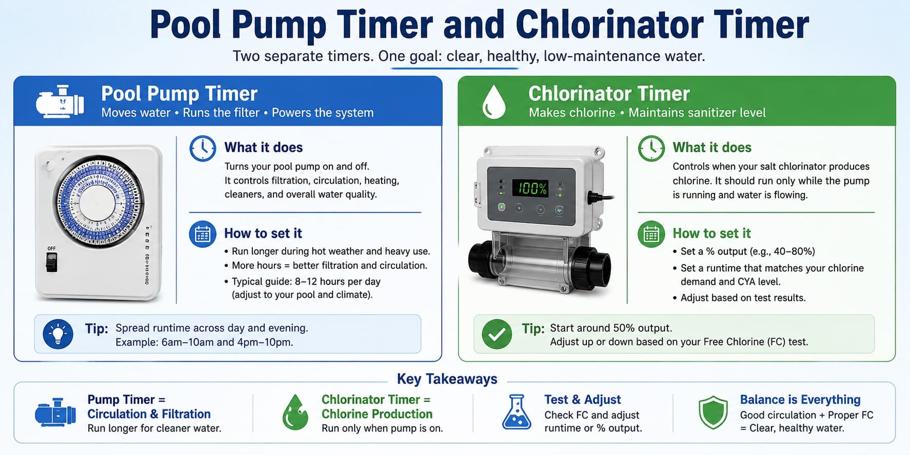
Separate timers, shared relays and integrated controls
Before changing any programme, identify how the pump and chlorinator are controlled. The correct approach depends on the installed arrangement rather than the brand name alone.
Separate timers
The pump and chlorinator have independent clocks or schedules. The chlorinator period should fit inside a pump stage that provides reliable flow through the cell.
Shared relay or switched supply
A single timer or relay controls when the pump circuit and chlorinator power are available. A separate chlorinator programme may not be required.
Integrated automation
A compatible controller manages circulation, pump speed and chlorinator permission. The relevant settings may be stored in one automation system.
Requirements differ between systems. The Jandy TruClear installation manual requires the power pack to be interconnected with the pump power source and describes the flow sensor as backup protection. Other systems may use shared relays, internal flow logic or digital communication. The manual for the exact installed model takes priority over a generic timer rule.
What must happen before chlorine is produced
A matching clock does not prove that the salt cell is operating. Four separate conditions must be satisfied.
How to sync separate pool pump and chlorinator timers
The example below illustrates the scheduling principle for two independent timers. It is not a universal recommendation for start delays or daily runtime.
The ten-minute margins are illustrative only. Some systems are designed to start from the same relay and require no independently programmed delay.
Checks to complete in order
- Identify every active pump programme, including priming, filtration, heating, cleaning and low-speed stages.
- Compare the current time and day shown by the pump, chlorinator and automation controller.
- Confirm whether the chlorinator has a separate timer or is enabled by a shared relay or controller.
- Observe a complete startup. Check that the pump primes normally and that the chlorinator changes to a generating status only after the controller accepts the flow condition.
- Observe shutdown and confirm that generation ends when circulation ends.
- Test free chlorine at a consistent time over several comparable days before making another production adjustment.
Timer terminals, relays, power supplies and fixed electrical connections are not owner-adjustment points. Energy Safe Victoria advises consumers to use appropriately licensed electrical workers for electrical installation work. A Certificate of Electrical Safety must be supplied where required for the completed work. See Energy Safe Victoria's electrical worker guidance and Certificate of Electrical Safety information .
Variable-speed pump schedules must provide enough flow
A variable-speed pump can remain on for many hours while operating below the flow threshold accepted by the chlorinator. The lowest RPM that keeps the pump moving is not automatically suitable for chlorine production.
A speed that clears the no-flow warning immediately after filter cleaning may become marginal as the filter collects debris or valve positions change. Skimming, heating, cleaning and chlorination can also require different operating speeds.
A no-flow warning can be associated with low RPM, low pool water level, air entering the suction side, a blocked basket, a dirty filter, valve position, restricted plumbing or a sensor problem. The message normally means that the detected flow is below the controller's accepted condition; it does not necessarily mean that no water is moving anywhere in the system.
Estimate nominal daily chlorine production
Output percentage cannot be interpreted without the cell's rated capacity and the time during which it is actually generating. A nominal calculation can help identify whether the programmed operating window is broadly capable of meeting demand.
Illustrative calculation: 20 g/h × 0.50 × 8 h = 80 g/day.
Generating time may be available from an automation history, a controller log or the period during which the display shows a generating status. If the system does not record operation, generating hours can only be estimated from the timer window, duty-cycle behaviour and observed warnings.
Actual production can be reduced by interrupted flow, salt or temperature protection, scale, ageing electrodes, controller limits and non-generating periods. The resulting free chlorine level also depends on pool volume, sunlight, stabiliser, bather load, debris and existing chlorine demand.
The meaning of the displayed percentage also varies between models. It may control a duty cycle, relative cell output or another manufacturer-specific operating mode. Check the model manual before treating the percentage as a directly comparable setting.
Common timer and flow symptoms
The causes below are starting points rather than confirmed diagnoses. Timer, flow, cell-condition and water-chemistry problems can occur at the same time, so check the operating sequence before changing runtime or output.
| Observed symptom | Possible timer or flow explanation | Check first |
|---|---|---|
| Chlorinator shows no flow when the morning programme starts | The pump may start later, remain in priming, run at insufficient RPM or fail to establish normal circulation. | Compare clocks, review the active pump stage and check water level, baskets, valves, filter condition and return flow. |
| Free chlorine falls although the display shows a high percentage | The generating window may be short or interrupted, or chlorine demand may exceed the cell's daily output. | Confirm generating hours, warning status, rated cell output, salt condition, cell cleanliness and the free chlorine trend. |
| The chlorinator display stays on after the pump stops | The controller may be powered in standby, or separate timers or relays may be incorrectly coordinated. | Read the exact controller status. Do not assume that an illuminated display means the cell is generating. |
| The schedule stopped working after a blackout | One device may have retained its programme while another lost its clock, day setting or active schedule. | Verify the current time, day, AM/PM format, enabled programmes and manual overrides on every controller. |
| No-flow appears only during part of the day | The pump may change to a lower RPM, or solar, heating, cleaner or pool/spa valve operation may alter flow through the cell. | Match the warning time to pump-speed and valve schedules, then observe the system when the warning appears. |
| Free chlorine rises for several days | The timers may be correctly synchronised, but daily production is higher than current chlorine demand. | Change one production control at a time and compare free chlorine at the same time of day under similar conditions. |
No flow when the morning programme starts
Free chlorine falls despite a high displayed percentage
The display stays on after the pump stops
The schedule changed after a blackout
No-flow appears only during one pump stage
Free chlorine continues to rise
Recheck synchronisation after seasonal or power changes
Reducing winter pump runtime may also reduce chlorine production if the chlorinator loses generating hours. Extending pump runtime can increase production only when the cell remains enabled and is not stopped by flow, salt, temperature or cell warnings.
After a blackout or electrical work, verify the current time, day, active programmes, pump-speed stages, chlorinator output and manual overrides on every controller.
Safe owner checks and electrical limits
Visible operating checks
- Compare the displayed time and day on each controller.
- Record every active pump start, stop and RPM stage.
- Read the exact chlorinator status message.
- Observe startup, visible return flow and shutdown.
- Check pool water level, baskets and visible valve positions.
- Test free chlorine at a consistent time.
Work requiring qualified electrical assessment
- Changing timer, relay or power-supply wiring.
- Moving conductors between terminals.
- Installing or changing an electrical interlock.
- Opening powered electrical enclosures.
- Bypassing a flow switch or other safety control.
- Investigating repeated electrical protection trips.
Isolate the equipment using the appropriate safe procedure and arrange qualified assessment if an enclosure contains water, conductors are exposed, there is a burning smell, electrical protection repeatedly trips or the cell appears able to generate without circulation.
Frequently asked questions
Should the pump and chlorinator timers show identical times?
They should show the correct current time, but their programmed start and stop times do not always need to be identical. With separate timers, the chlorinator period should remain within a pump stage that provides suitable flow. Shared-relay and integrated systems may not use a separate chlorinator schedule.
Can the chlorinator controller remain powered when the pump is off?
Some systems can display standby information while the cell is not generating. The important question is whether chlorine generation is possible without circulation. Check the model manual and the exact status shown on the controller.
Why does the chlorinator show no flow while the pump is running?
The active RPM may be too low, or circulation may be restricted by low water level, air entry, a blocked basket, a dirty filter, valve position or plumbing resistance. A sensor fault is possible, but it should not be assumed before checking the hydraulic conditions.
Should runtime or output percentage be adjusted first?
First confirm that filtration, skimming and estimated generating time are adequate. Then change one production variable at a time. Changing runtime and percentage together makes the resulting free chlorine trend difficult to interpret.
Does correct timer synchronisation guarantee enough chlorine?
No. Synchronisation only creates a valid opportunity for the cell to generate. Actual free chlorine also depends on rated cell output, salt condition, water temperature, cell condition, pool volume, sunlight, stabiliser and chlorine demand.
Manufacturer and safety references
The references below support general operating principles and selected model-specific examples. They are not interchangeable wiring instructions. Use the installation manual supplied with the exact pump, chlorinator and automation system installed at the pool.